 |
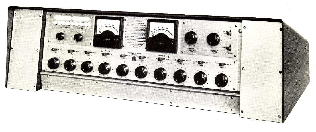
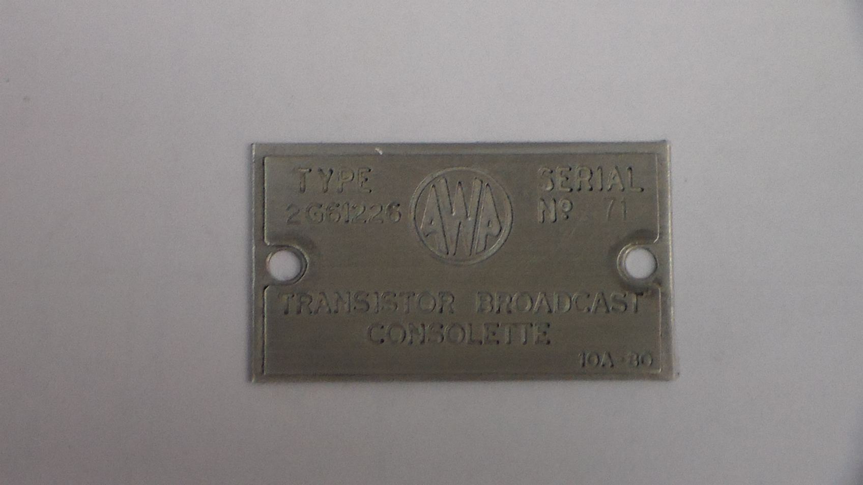
AWA Consolette BAC-1 2G61226 |
Download Documents
BAC-1 Manual AWA Brochure Power Supply Mods VU Meter Pad New Mute Circuit 30dB Amplifier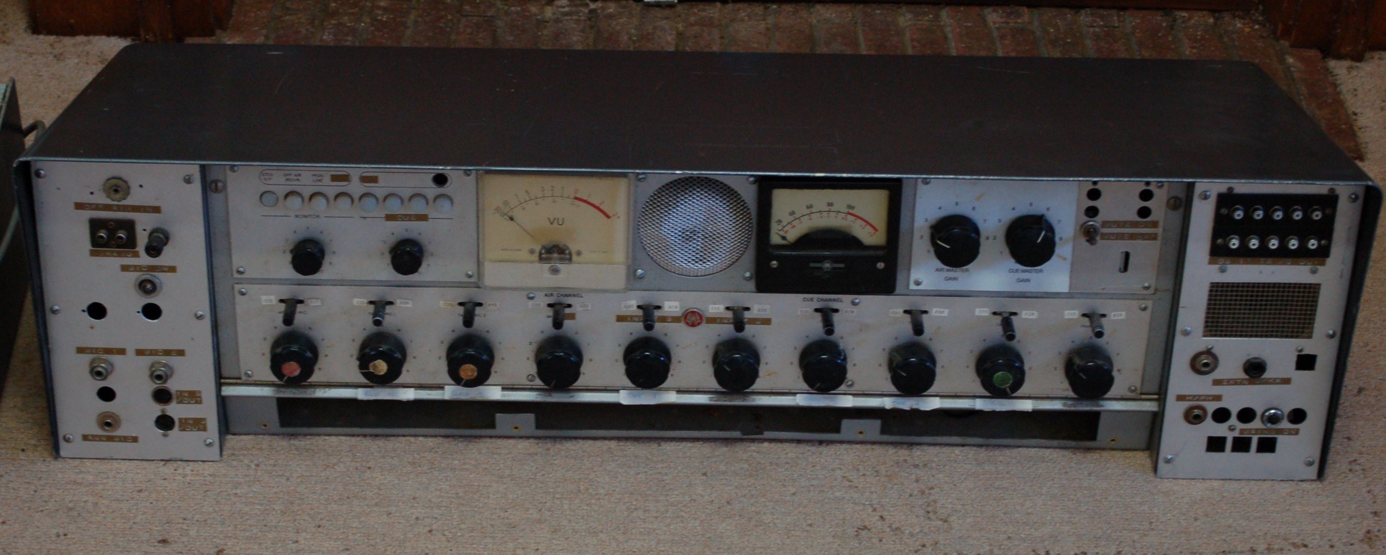
Recently an old school friend was clearing out his shed and an AWA BAC-1 came my way. This console has been modified several times over the years so it needs a fair bit of work and a few spare parts to bring it back to what you see below.
Externally there isn't too much to do as the BAC-1 was designed to be customised and many of the face plates can be replaced with newly cut panels. Further, as these consoles were customised I have no problem doing some of my own customisation as long as the parts I use are in keeping with 1960's-70's.
The first step in the restoration was research. Information about the console was sort and an assessment of what parts needed repair or replacement. A manual was found on-line but this was for an ealier model which used much of the same circuitry but at an overall system level there were a number of differences. Interestingly, much of the circuitry in my BAC-1 used Silicon transistors where as the circuitry in the manual used Germanium transistors but apart from this there were few other differences. A number of the modules had serial numbers of 1 or 2 but the BAC-1 serial number was 71.
I thought that this may have been the point when AWA changed technology from Germanium to Silicon. Stephen Langley kindly scanned his copy of the BAC-1 manual which I have cleaned up an is now available for download. This version of the manual covers serial numbers from 102 and in this document specifies Germanium transistors in the circuitry. So I expect that the amplifier modules in my BAC-1 came from a BAC-1 made much later.
Back to the assessment of the condition of the BAC-1. Firstly, it was in need of a good clean. Then quite a few of the shielded cables needed replacing as the insulation had be scraped off. At one point the electronics had been converted from balanced to unbalanced with many of the transformers being removed.
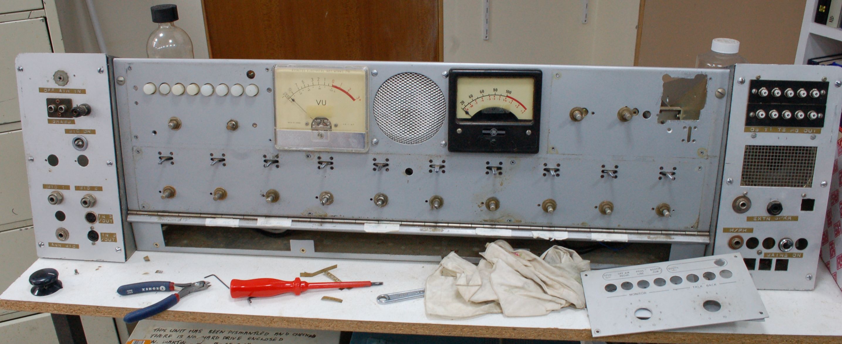
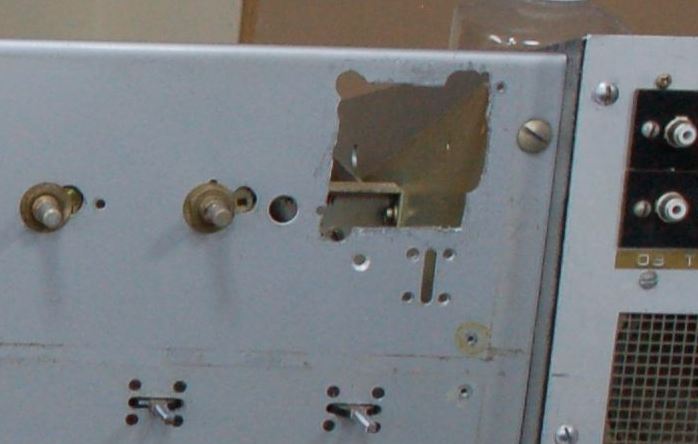
One of the first jobs was to remove all of the knobs and switch caps so that the face plates could also be removed giving me a better look at the holes that had been hacked in the main panel. All of the unwanted holes can be covered with some new face plates so patching these holes isn't necessary, however, the large nearly rectangular hole (upper right) will be patched as panel space is needed for re-mounting of the utility key switch and hole is where the utility key switch was originally located. Later on I'll go into the detail of the panel repair.
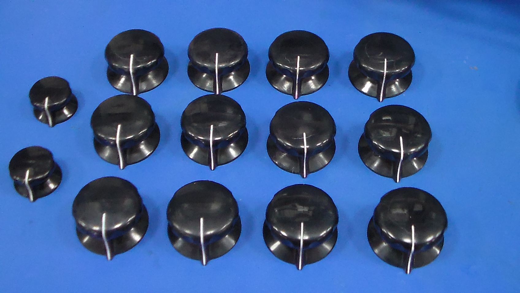
Next the knobs where polished, there is plenty of information on the web about polishing Bakelite so I won't waste time here on this part of the restoration. These knobs still have some surface cracks after polishing but that's okay because you can see that there is some age to them. The pointers of the knobs were filled with White Lacquer Stik, p/n 51120. I'm not about making the console look brand new, rather just cleaning it, removing some of the hacks, and making it functional.
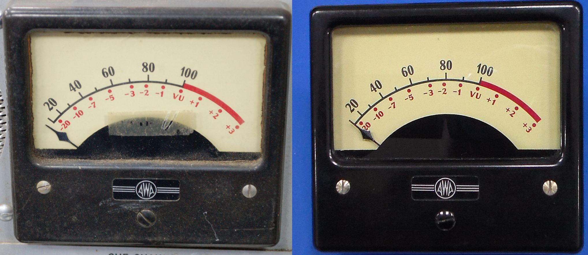
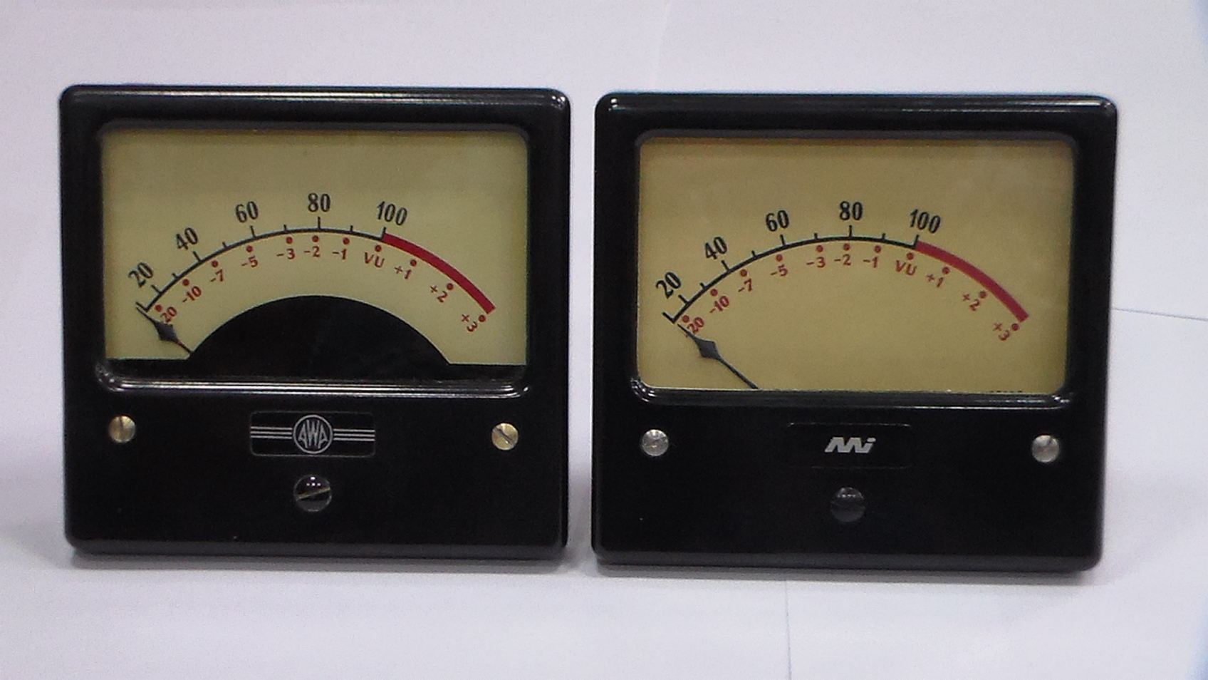
Here is a before and after shot of the original VU meter apart from gerenal cleaning and polishing not much effort was required to bring the VU meter back to almost original condition. This VU meter was manufactured by Master Instruments (MI), the standard meter usually had a VU "A" scale where as the one for AWA had a VU "B" scale. The AWA version has a semi-circular black mask on the bottom of the meter glass and an AWA decal on the front cover instead of a MI decal. As I don't have another original AWA VU meter I'm modifying an original Master Instruments VU "A" meter.
Meter Conversion
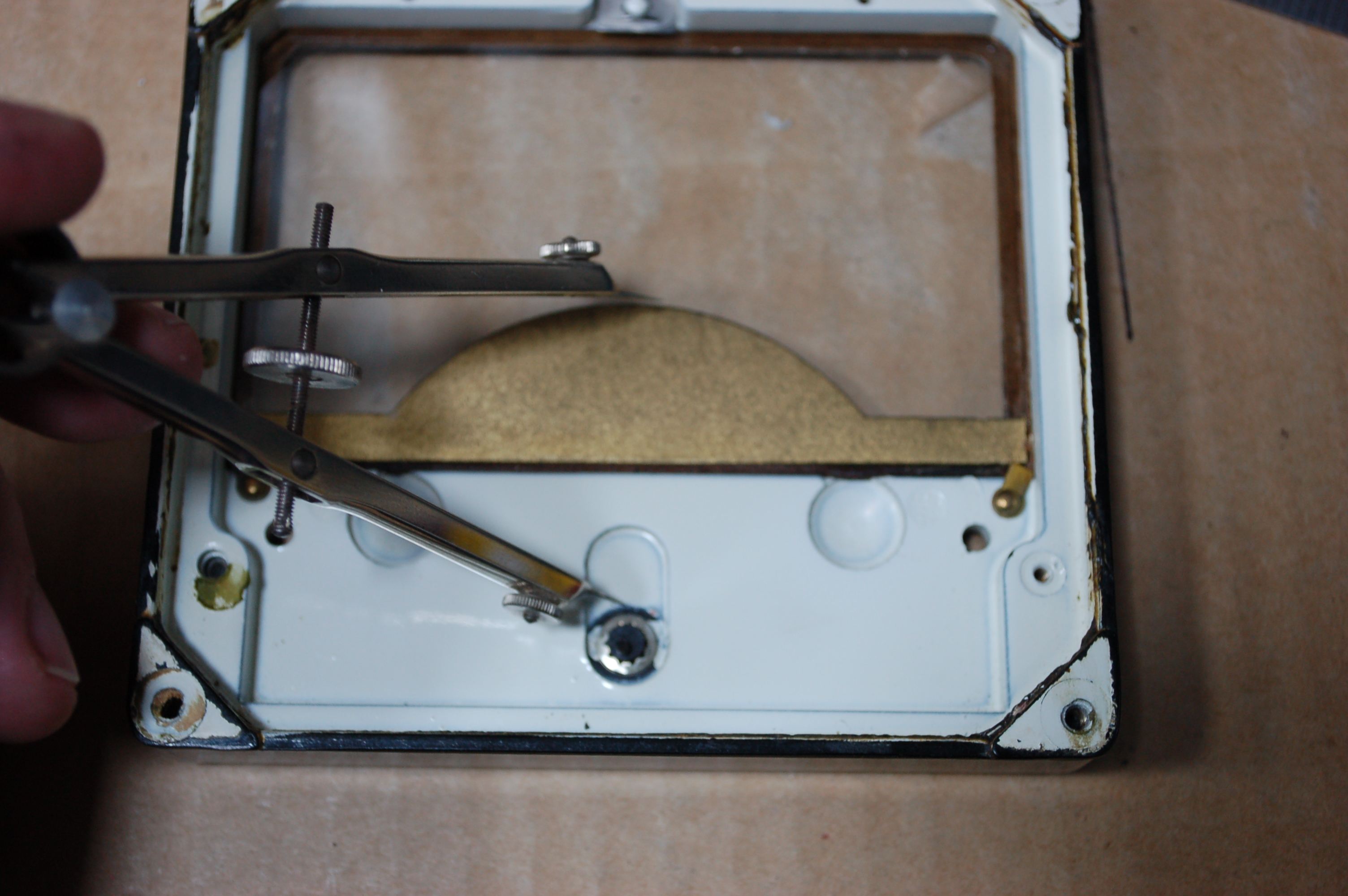
Step 1, in converting the standard MI VU meter into what was built for AWA. I removed the VU "B" scale from the AWA VU meter and scanned it so I was able to reprint the scale on high quality paper. A number of prints were made with gradual changes to the RGB mix so that it was possible to get a close colour match with the original meter scale.
The procedure for fitting the new scale is as follows:
1. Carefully remove the scale plate from the meter.
2. Print the new scale on higher quality paper than would normally be used and select the highest quality printing mode (usually the slowest).
3. Carefully cut off the excess paper, don't cut any curves with scissors if the edge won't look clean. Curves can be done later.
4. Take the existing meter scale plate and place it face down on a clean surface, using the back of the scale plate for the new scale means that old scale can be used in the future if required.
5. Using thin double sided sticky tape apply the tape to all the edges of the plate making sure not to overlap any pieces of tape as this cause ridges to be visible on the surface of the new scale. Also place a few pieces of tape near the centre of the scale plate.
6. You should have enough cut edges on the new meter scale to make it easy to align with the edges of the scale plate. So start fitting the new scale smoothing out any ridges as you go.
7. Once the scale is fixed in position any excess paper not cut off earlier can now be removed with a scalpel. Make sure you are using a new blade and cut away any excess paper using the edge of the scale plate as a reference. When cutting only cut a small section by pushing the blade away from you, don't cut while pulling the blade back as some of the scale paper my lift and/or cause a rough edge on the paper.
8. When refitting the scale plate to the meter movement you may find that there is a slight misalignment because the scale plate has been flipped over, mostly the issue will be that the plate is fouling on one of the lamps. As this part of the scale plate is not seen through the viewing window the plate can be carefully filed in the area of the lamp to make it fit.
Step 2, mask the meter movement. While there isn't much that needs masking AWA decided paint an arc on the meter glass which masks off the lettering at the bottom of the meter scale which indicates the meter was manufactured by Master Instruments. The easiest way to make this mask was use adhesive tape as a stencil and spray paint the inside surface of the meter glass with high gloss black paint.
Stencil for the Meter glass:
1. With the original meter bezel and drafting dividers the radius of the arc was measured as 1 7/16". The dividers have a number of useful features, (i) the distance is fixed by the thumbwheel, (ii) the sharp points can be used to scribe an arc.
2. Clear wide adhesive tape is applied to the inner surface of the meter glass. Make sure to clean the glass before applying the tape and remove any air bubbles or creases as the tape is applied.
3. The dividers can now be used to scribe the arc. In this case the arc ends 1/4" from the edge of the glass at each end of the arc.
4. Two horizontal lines are then cut with a scalpel from the ends of the arc to the edges of the glass.
5. The tape covering the area to be painted can now be removed.
6. Carefully remove any adhesive left on the glass when the tape was removed.
7. Apply tape to any other parts of the meter bezel to mask any unintended over spray of the paint.
8. Spray two light coats of black gloss.
9. Carefully remove the tape and under magnification use a scalpel scrape off any small defects.
Step 3, AWA logo on the meter bezel. I didn't want to go to the trouble of making the logo plate, but fortunately these can be found on some AWA equipment which use a large meter. The logo plate used here came from junked AWA Voltohmyst, $25 on ebay, cheaper than getting one plate costom made..
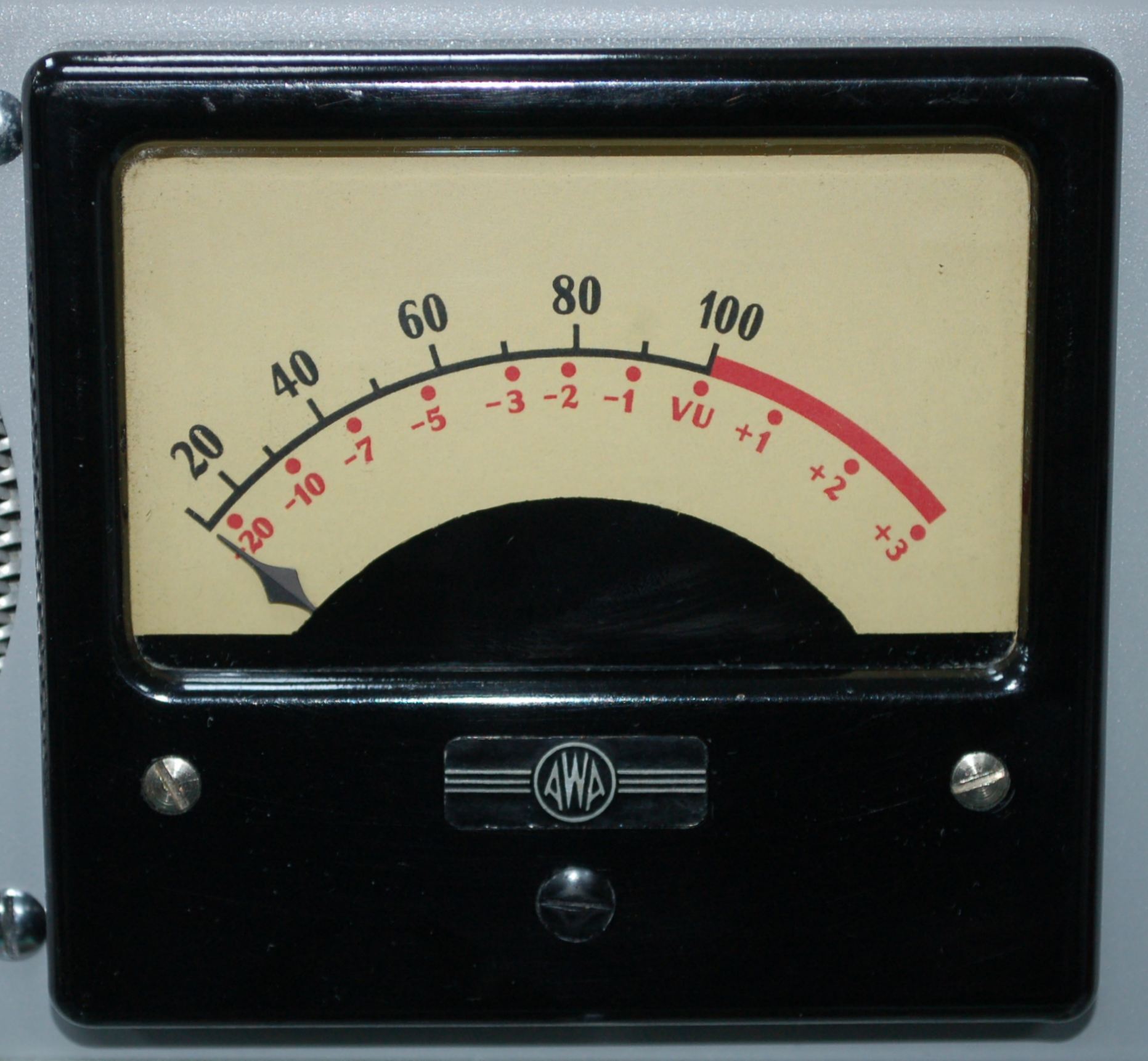
The only issue I have with this modified meter is the fact that the needle or pointer is slightly shorter than that of the meter that came with the console. As I don't have the skills or tools to change the needle length without causing major damage to the meter movement it is best left as is for now. I have had a closer look at some of the advertising pictures for the BAC-1 and in some the meters on the console have slightly different pointer lengths so this issue is not as important to me now.
Metal Bashing
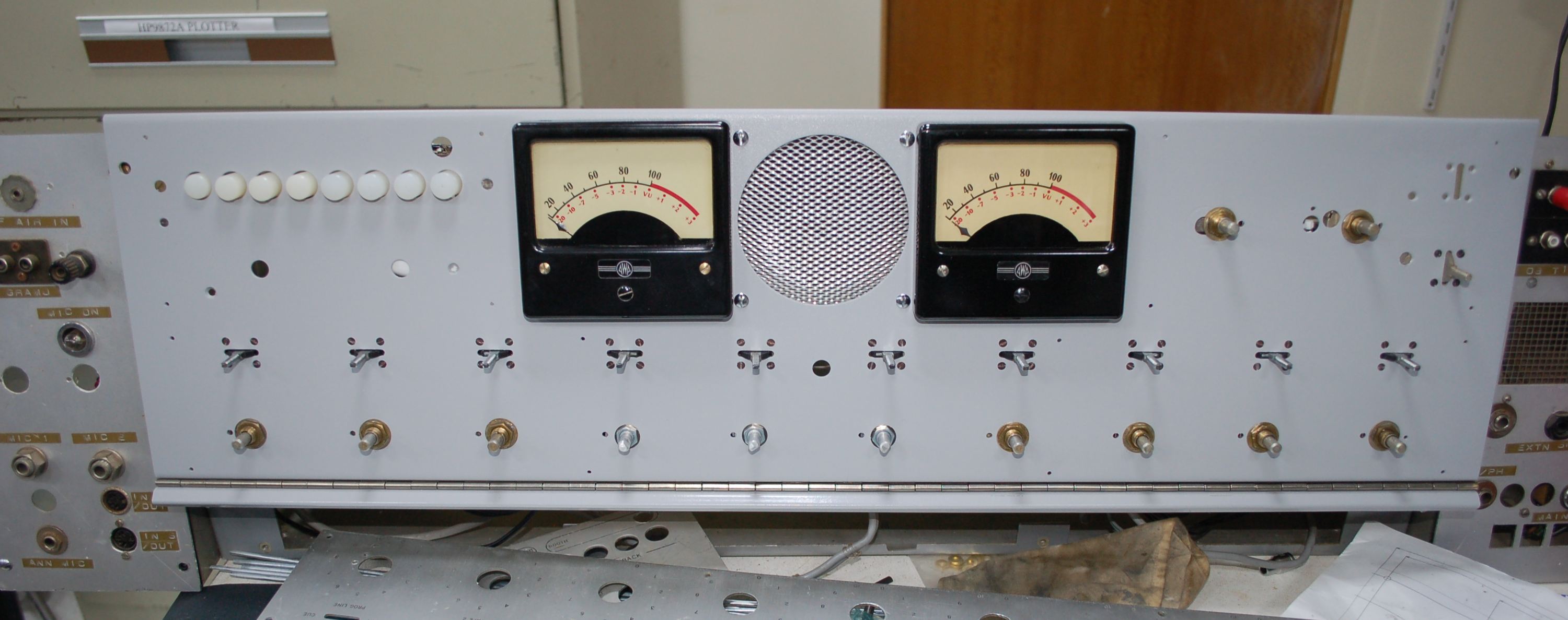
One of the issues that needed addressing was the large hole cut in the front panel, this hole could be covered with a new face plate but as part of the restoration was to re-mount the "Utility" key switch mounting holes were required on the main panel. Here is the panel before restoration.
With the componentry removed an aluminium plate was cut with a profile similar to the hole. The plate was clamped in position then soldered using Durafix then the excess Durafix was milled off and the surface sanded back.
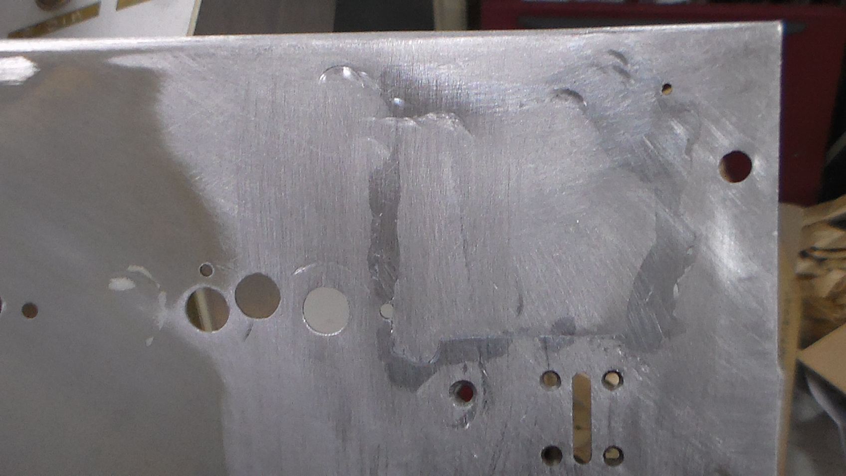
Then a new slot was milled plus mounting holes for the "Utility" key switch. The bare metal was etch primed and filler was used to fix the surface imperfections. Finally, the closest match to the original paint colour I could easily find was Dulux spray paint "Endless Dusk". From the colour chart showed that the paint should have been a shade darker than the original gray but the paint was in fact a shade lighter. The image below shows the finished panel with most of the controls re-installed.
July 2016 Update
For the past few weeks I have been getting together some parts and materials so I can move forward with the restoration/rebuild work.
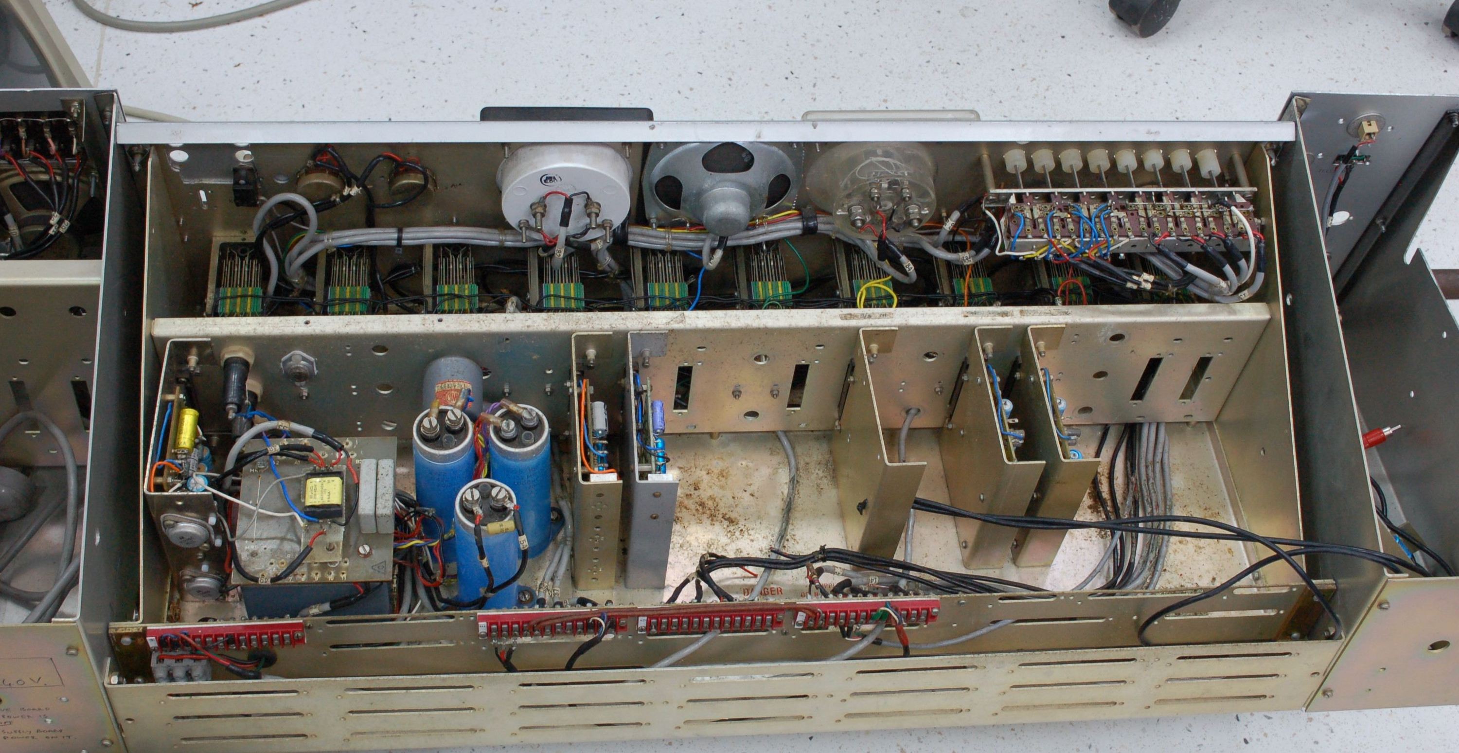
Power Supply
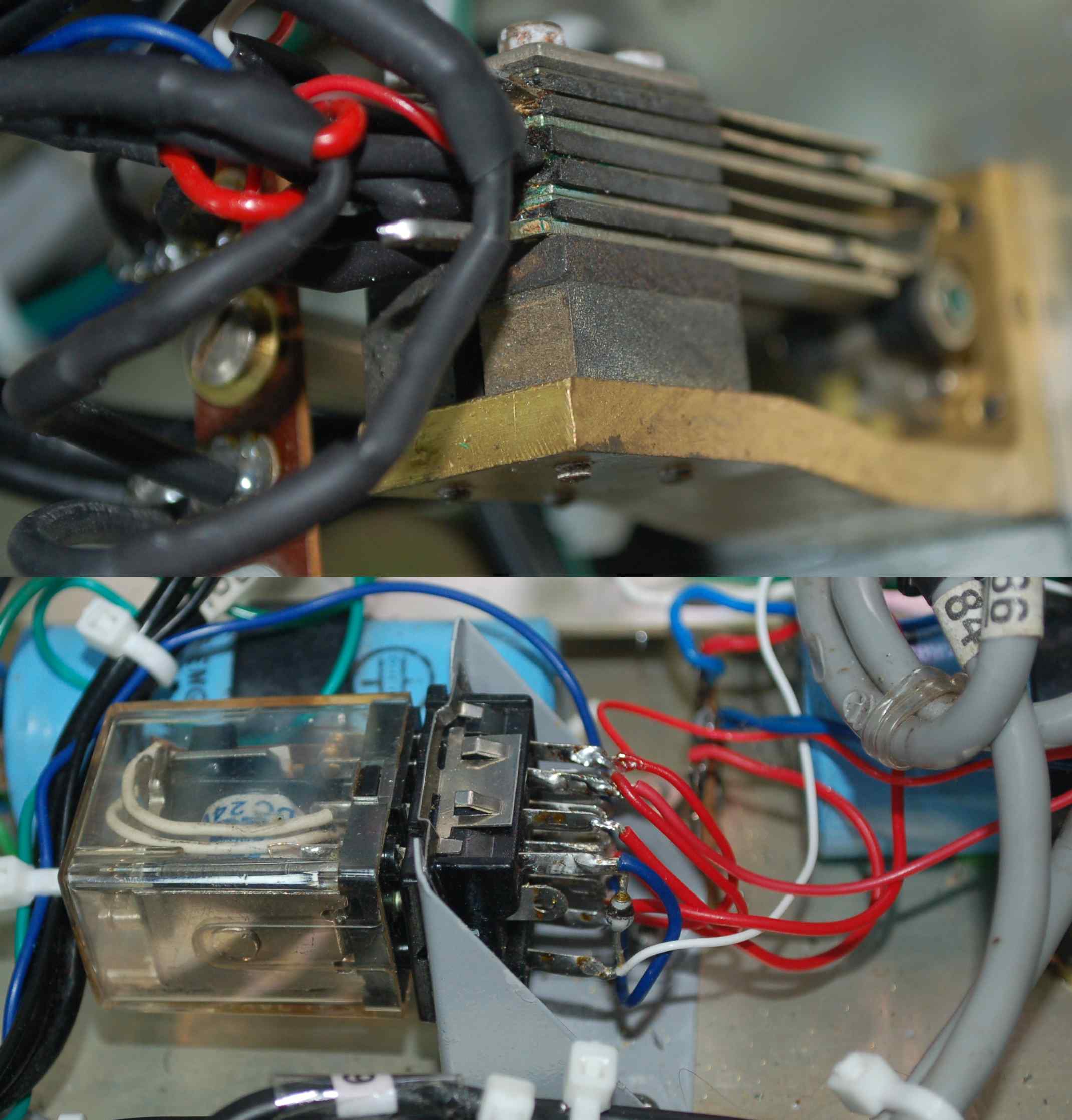
The first part of the electronics that needed attention was the power supply. The initial work required here was to make sure the mains connection to the transformer was safe, then check that the correct rail voltages were being generated. The original -24V regulator circuit was a very simple design and it had one obvious failure mode and a design flaw. The failure was as C3 ages the output voltage can be pulled toward 0V. This had started to happen so I replaced the capacitor. This is when the design flaw kicked in, I was testing the power supply with no modules plugged in so the output of the regulator was "unloaded" except for two supply bypass capacitors located on the chassis near the line output module sockets. Without a load on the regulator the output voltage floats up to almost the same value as the regulator input voltage. This wouldn't have been an issue but for the fact that the bypass capacitors are rated at 25V and the regulator input voltage wasn't the nominal -25V as indicated on the schematic but it is more like -31V. I've made some small changes to the regulator to give better regulation, reduce the component aging issue and add some load at the regulator output to stop over voltage with light loading. For the modified schematic click here..
Line Amplifiers
The line outputs have been the next area for me to tackle. As the output transformers were missing replacements had to be found. The first step was to power up the 50dB line output amplifiers on the bench and make some measurements. The original specification for the maximum "undistorted" output and the measured output direct from the line amplifier module allowed the output transformer turns ratio to be calculated. Also knowing the approximates size of the original transformer I started searching for a suitable replacement. After finding some candidates I selected the Sowter 8403a.
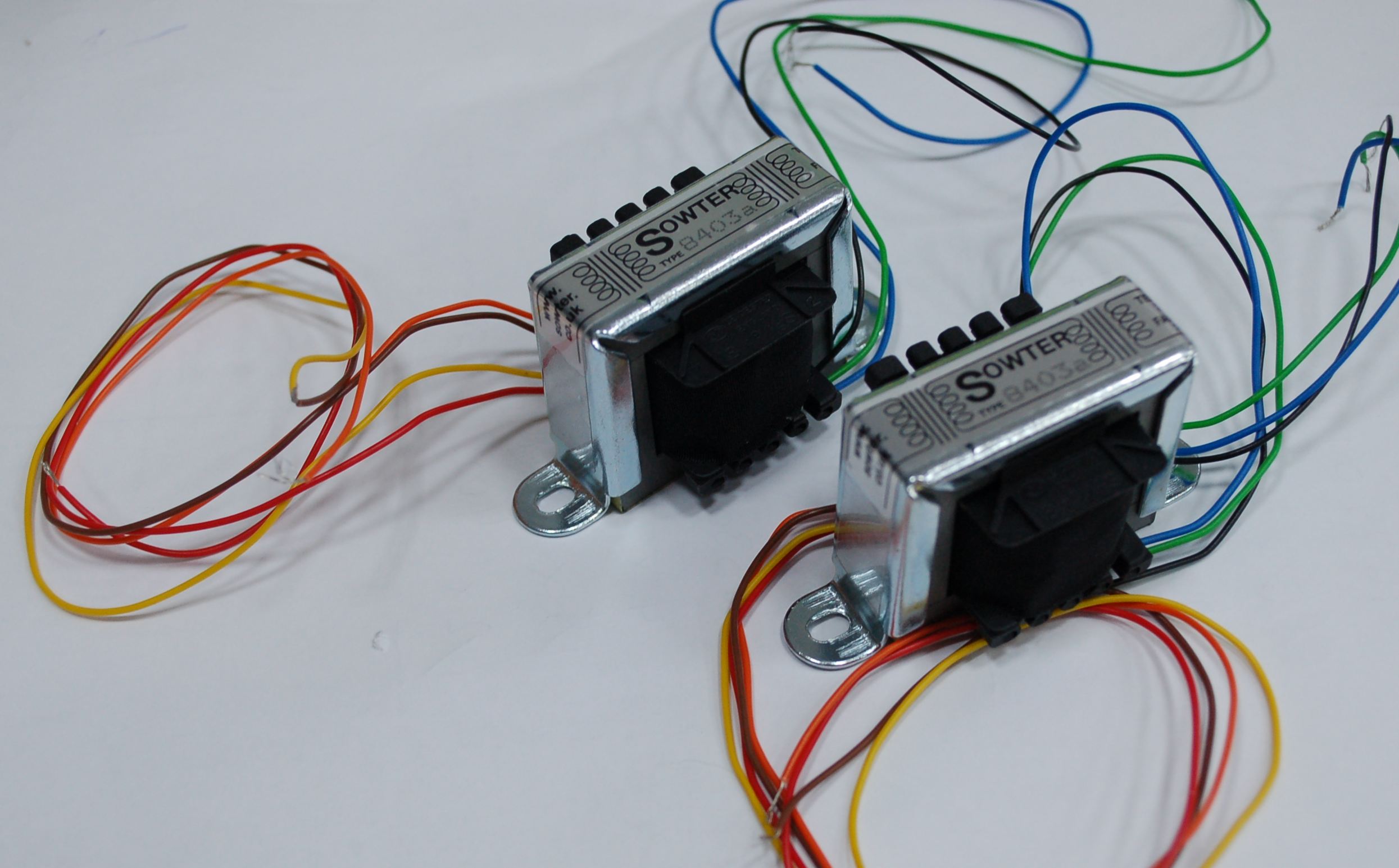
When the transformers arrived I continued the bench testing the line output module with the 8403a, for high frequency stability a capacitor needs to be connected in parallel with the secondary winding, 47nF was found to be a good compromise but is a some what larger value than used with the original transformer, DOH! I wasn't terminating the line, with it terminated the original value of 10nF was fine. Shown below is the line output amplifier under test with the 8403a connected.
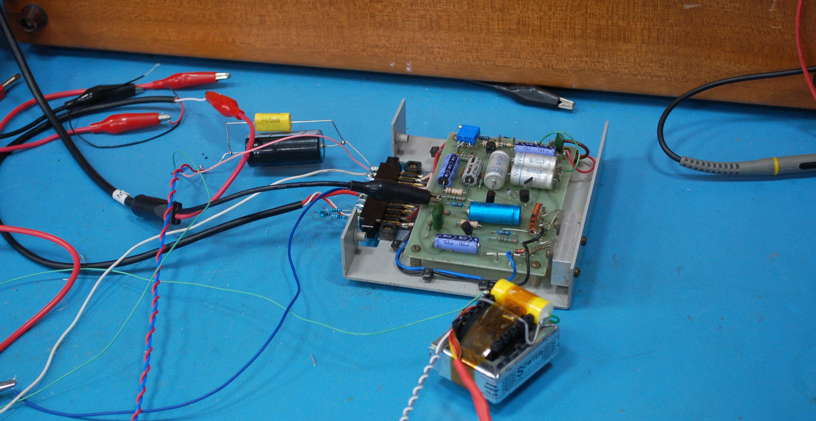
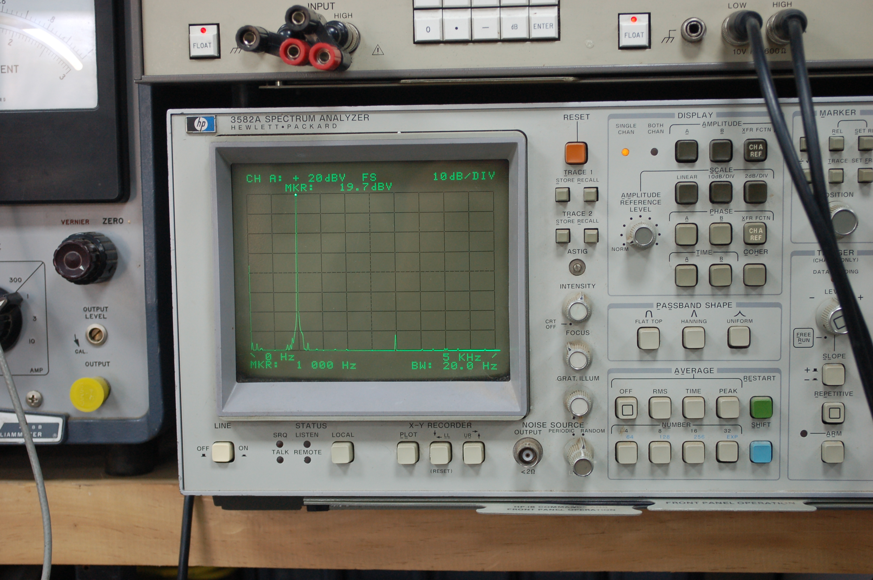
While under test adjusting the bias pot on the line output amp. was found to be tricky particularly when adjustment was made close to clipping and the aim was to minimize all of the harmonics I could see on on my HP 3582A Spectrum Analyzer. So to make the bias adjustment easier the original bias pot was replaced with a 50k multi-turn trimmer, it is located near the top left corner of the PCB in the above image. This 50+ year old line driver design at +20dBm output into 600ohms has mainly 3rd harmonic distortion at 70dB below the fundamental and the distortion is comperable with the system noise at normal operating levels. In the image below the measurement was made at +20, if a +24dBm measurement was made the 3582 input sensitivity would have to be +30dBm and this would have made it hard to read the 3rd harmonic.
As with many other parts of this console the NORMAL/EMERGENCY key switch had been removed along with relay C. These parts allow the channel 1 and 2 line amplifiers to be swapped, the idea is that if channel 1 fails you can replace it with the channel 2 amplifier just by selecting the EMERGENCY position minimising any interruption the programme going to air.
A braket was fabricated for the relay and the parts were install and function tested.
VU Meters Again
Based only on my BAC-1 it would appear that BAC-1s with a serial number below 102 didn't have a pad for each VU meter. With a pad each meter can be precisely calibrated, so I decided to add this feature to my BAC-1.
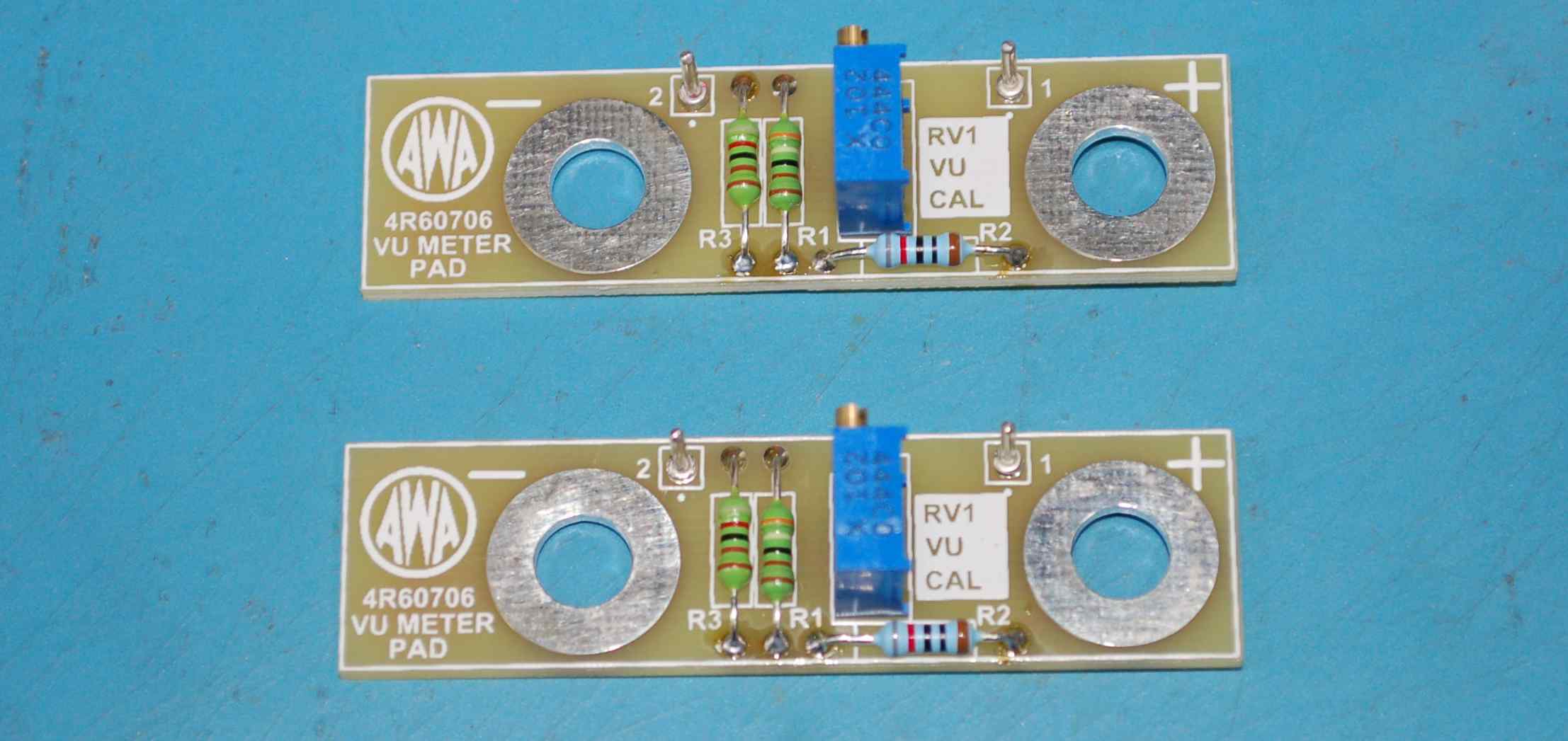
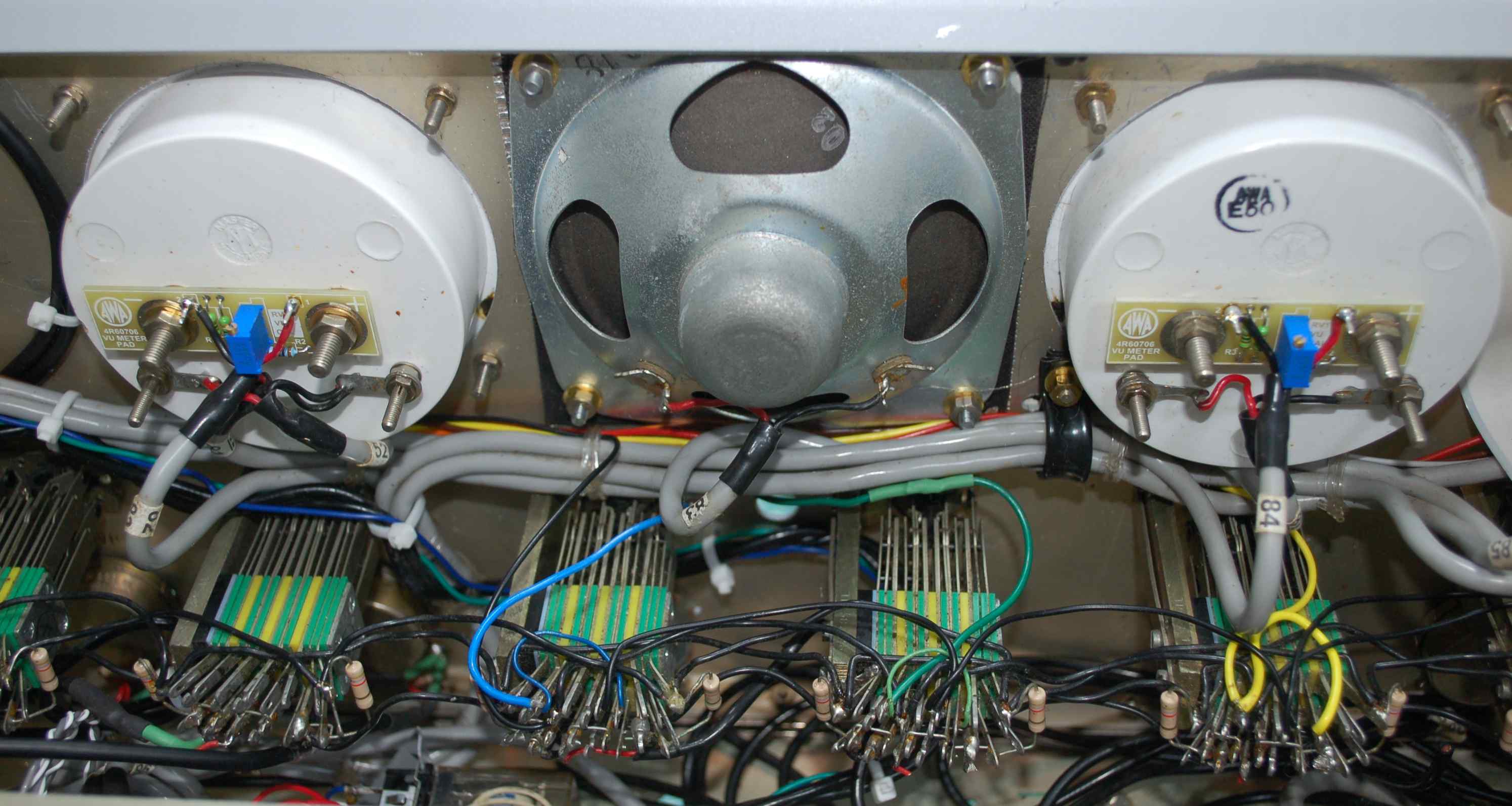
Here are two preassembled VU Meter Pad PCBs which I designed and they include the original AWA part number 4R60706 and the AWA logo. The mounting holes for these boards are made for the meter input terminals so the board mounts and makes connection to the meter movement, only the input wires have to be soldered to the board. Below you can see them installed on the VU Meter terminals. The style of trim pot was chosen so that screwdriver adjustment is at the top making it easy to adjust while viewing the meter and while the meter is in the normal operating position. Details of the VU Meter Pad can be found here.
Muting
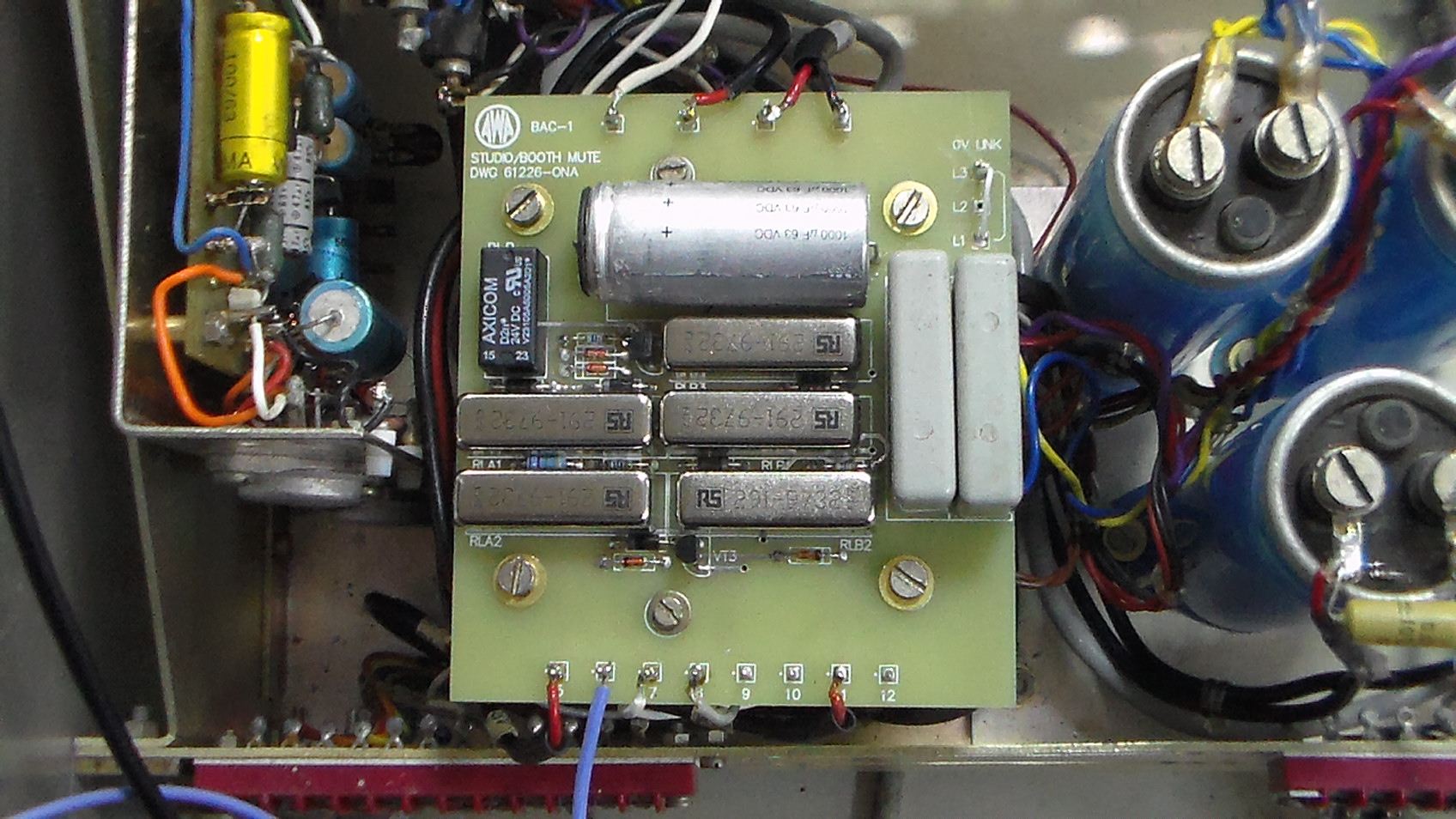
The BAC-1 has some reed relays which are used in muting the monitor amplifier and monitor speaker to stop feadback from microphones in close proximity to the monitor speaker or speakers driven by the monitor amp. The original circuit used both normally open (NO) and normally closed (NC) reed relays. As the original relays were missing and the replacement was faulty I looked into my options for replacement parts. The NC part requires a bias magnet and because it is likely that not many are made the price is quite high AU$65-100. A selfcontained 24V NO reed relay with a 1A contact rating is approximately AU$15 and as the NC function isn't required when power is off a transistor can be used to invert the NO operation to an NC operation. A new PCB has been designed using only normally open reed relays and some transistors to invert the operation some relays. Additionally some diode logic and a large timing capacitor have been included to force an 8 second power on mute which suppresses the power on thump from the monitor amplifier. To see the schematic and PCB layout for the new mute circuit click here.
April 2018 Update
Back in early December 2017 I was given another BAC-1, many thanks to Stephen Langley for his kind donation. My initial intention was to also restore this console as well but the corrosion on all of the internal metal panels is such that a complete disassembly is required so that all the metalwork can be sand blasted and replated. Also much of the electronics is badly corroded and it was heavily modified for stereo operation. As it needs a full strip down for a future restoration I decided to use it as a parts donor to my current project. Transformers and some barrier terminal strips are the parts required and I have some alternative transformers that can be used if some additional original parts don't come my way before I start the second console project.
Major Progress
During the last few weeks I have been installing transformers, ceramic standoffs, module connectors, barrier terminal strips, and all the wiring in between. I've taken quite a bit of care to make the looms neat and all shielded cables have wire numbers near each termination point to simplify any future fault finding. As much as possible the wire numbers line up with what was installed originally. This next image shows the wiring between the microphone amplifier module sockets and the input transformers, also from the primaries of the microphone transformers back to the barrier terminal strips on the rear of the BAC-1.
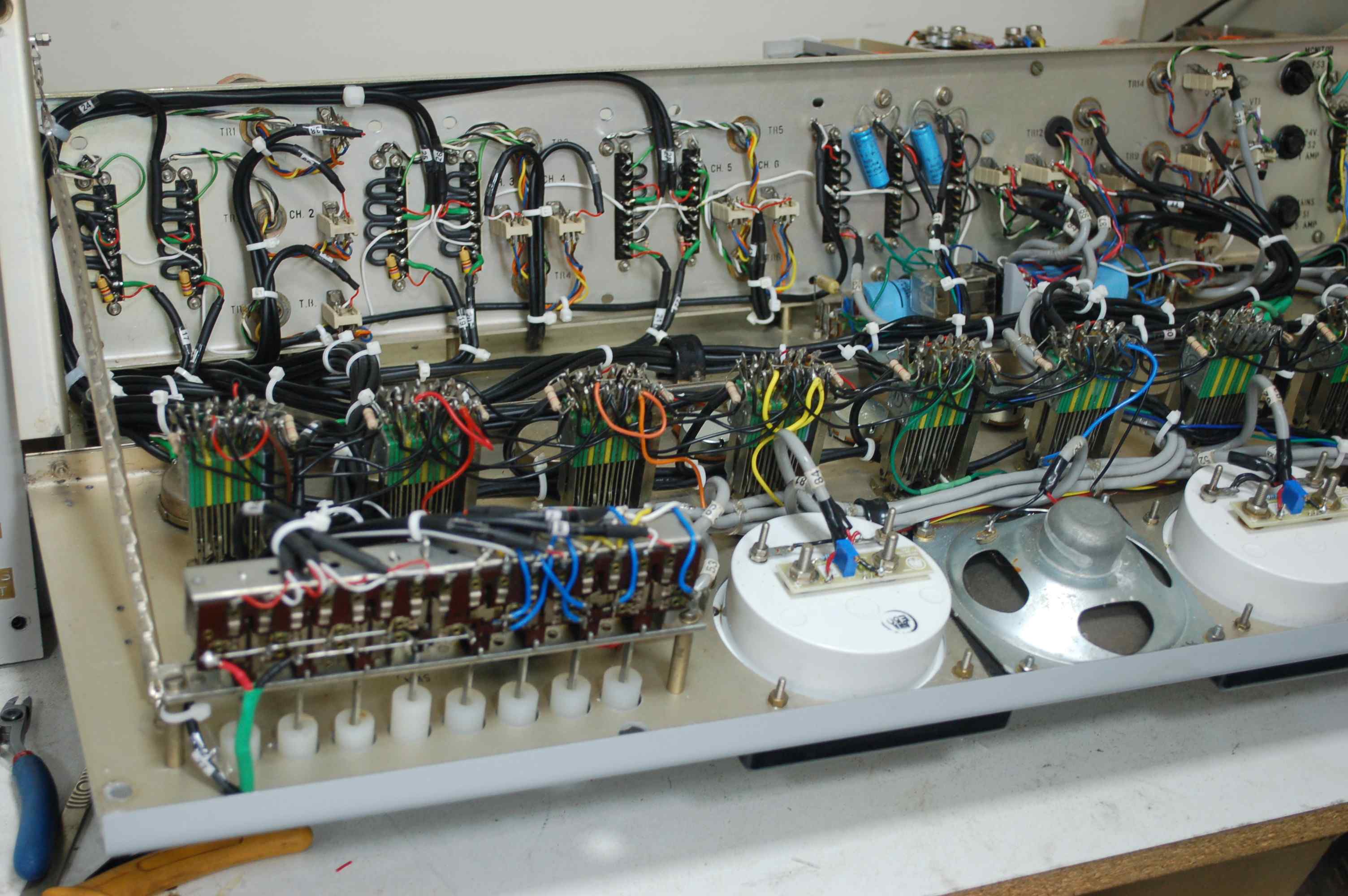
Microphone ampflifier modules
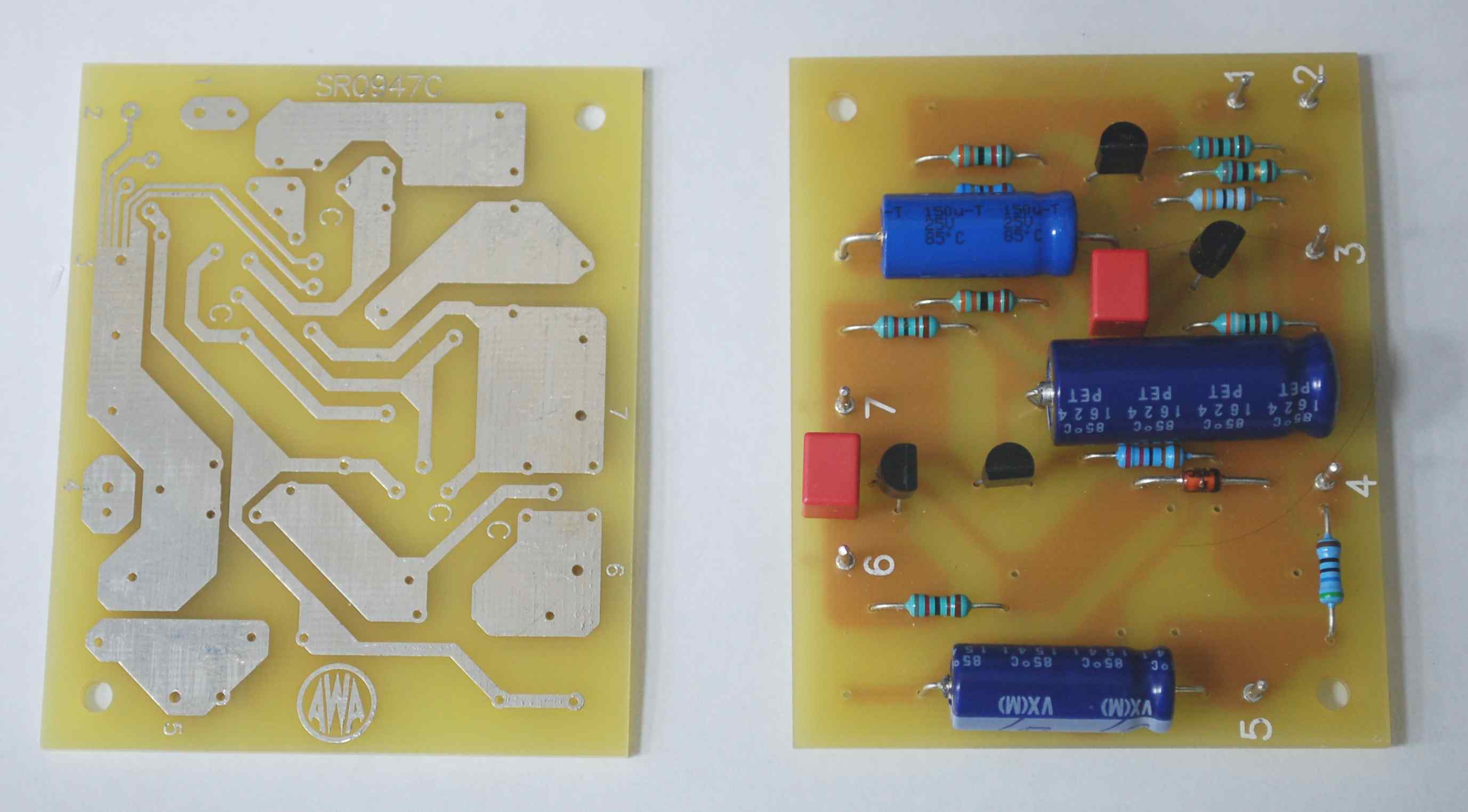
These modules use two circuit boards each board is an amplifier with 30dB of gain. The channel fader is placed between the output of the first amplifier and the input of the second. An input matching transformer is used to provide a low impedance input of either 50 or 150 ohms depending on how the transformer primary is connected. When there is corrosion and/or moisture associated with any PCB the circuit is likely to have issues in the short to medium term. When low level signals are involved as well then an increase in noise is quite likely to occur. Over the years I have seen too many issues of this sort so I decided to roll my own amplifier boards for this part of the restoration. In keeping with other boards I've designed for this project I tried to keep to the techniques used when the BAC-1 was designed so that the look of the new boards isn't out of place. The image below shows two 30dB amplifier PCBs the unplopulated one left is to show the track pattern and the one on the right shows an almost completely assembled board. Details of the board can be found by clicking here.
As the restoration progresses this page will be updated.