 | Byer 77 Tape Recorder |
The Byer "77" was the first Australian designed and manufactured tape recorder intend for use in professional recording applications. In December 1954 this tape recorder was officially released to the local market however, the advertising would indicate that field testing of the unit had been underway for approximately six months. It is not clear when production of this model ceased, the Byer "77" Mk II was released in early 1957 but there is some evidence that production of the Byer "77" may have continued into the early 1960's.
Reliability was the first priority in this design, the machine was solidly constructed using cast aluminum for most of the specialised mechanical components. To ensure the long term reliability the use of perishable rubber components was kept to an absolute minimum. The pinch roller was the only component in the standard tape deck that used any rubber as drive belts had been eliminated by using direct drive motors for the capstan and the spools. However, if the long play adaptors were used then these were belt driven by the spool motors. When the Mk II series was released this model was then known by the broadcasting and recording industry as the Byer "77" Mk I. The features of the unit are:
1. Direct drive capstan and spool motors (no belts).2. Push button / solenoid operation.
3. Speed 7 1/2 and 15 ips.
4. "S" shaped tape threading path.
5. Spool locking caps.
6. The amplifier, and deck are 19" rack mountable.
7. Remote control socket, for "STOP", "START", and "REWIND" functions.
8. Adaptor arms to allow the use of 10 1/2" spools.
9. 600 ohm balanced input and output.
10. Balanced inputs for both microphone and high impedance line.
11. Mu-metal head cover for the Replay head.
12. VU meter with very good transient indication.
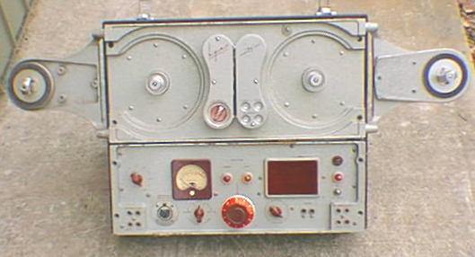
The Byer "77" Deck
The tape deck of the Byer "77" is very basic, there is only one rotary control which allows speeds of 7 1/2 or 15ips to be selected and four push buttons "STOP", "START", "REWIND", "FAST FORWARD". Record or play mode is selected on the amplifier panel. There is neon lamp on the upper right of the deck which indicates that the pinch roller is engaged. Access to the head block and pinch roller can be obtained by removing the two covers in the centre of the deck, these covers are fastened by captive screws. The remote control socket is located on the rear of the deck along with a switch which allows the capstan motor to run continuously or only when the "START" function is used. If the capstan motor is put in motion prior to playing or recording there is no speed up interval, only a small amount of instability in tape/head contact for a brief period when the tape motion commences.
The Byer "77" Amplifier
The amplifier panel has three types of balanced input, 50 ohm for a microphone, 600 ohm line level, and 100 kohm bridging input. All of these inputs are connected to a single input transformer, the 600 ohm and 100 kohm connections incorporate fixed attenuators so that similar signal levels result from each input.
To the left of the VU meter is as a switch which allows the operator to select the input to the meter. Normally the audio signal is selected however, if there is a problem other voltages in the circuit can be monitored to isolate the possible cause of the fault.
The amplifier has three modes of operation "RECORD", "PLAY", and "AMPLIFIER". The function of the "RECORD" and "PLAY" modes is obvious, the "AMPLIFIER" mode is in fact the "RECORD" mode but the bias oscillator and record amplifier are not in circuit so no signal can recorded.
In the centre of the panel is a 0 - 50dB stepped attenuator which is adjustable in 1dB steps. This attenuator is used to set the amplifier gain regardless of operating mode.
To the right is the monitor speaker and associated volume control. Unlike the later Mks of the model "77" tape recorder this one did not have tape/source switching on the line output channel even though the deck has separate record and reproduce heads.
The tube complement of the Byer "77" amplifier is:
1 x 5Y3GT, 1 x 12AT7, 2 x 12AU7, 1 x 12AX7, and 3 x EF86.
The Byer "77" with 10 1/2" spool adaptors
When extra playing time was required adaptor arms were fastened each side of the deck to allow the fitting of 10 1/2" spools. The hubs on the adaptor arms are grooved to locate a drive belt, there are similar sized grooves on the hubs of the spool motors to accept the belts. The spool centres are not NAB standard, they might be the same as those used on the German Magnetophone but as yet I have been unable to verify this. If the use of adaptor arms so that large spools can be used seems familiar then it is not surprising as Magnecord Inc of Chicago used a similar arrangement with their recorders. Byer Industries probably used the idea in their machine because they had been manufacturing the Magnecorder in Australia under license.
Pre-delivery testing
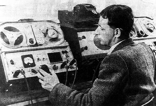
Jack Richardson (Byer factory foreman) testing Byer "77" recorders prior to delivery to the ABC for use at the 1956 Melbourne Olympic Games. (Electronics Australia, Aug 1995)
Byer 77 on Swaggie Record Sleeve
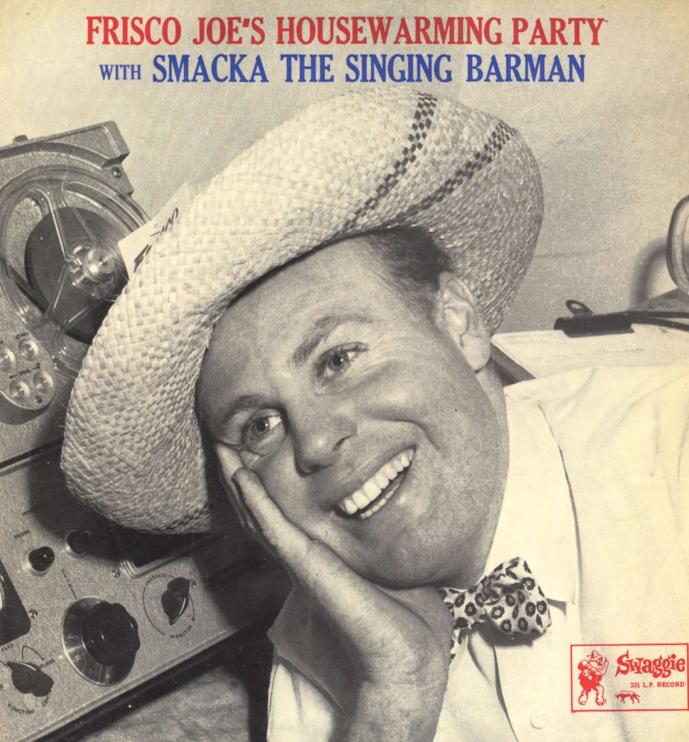
It's not often that you see recording equipment on record sleeves and especially not Australian made equipment. As I also collect Australian Jazz, this particular album is a nice bridge between the equipment and record collections. For the pro audio guys the Engineer on this LP just happened to be Bill Armstrong.