 |
Byer 66 Mk II Tape Recorder |
The Byer "66" Mk II was first released in late 1956 and production continued till the mid 1960's. Even though Rola (Aust.) Pty. Ltd. purchased Byer Industries in late 1957 it was a few years before the Model 66 Mk II was re-badged to the Rola "66" Mk II.
If you are restoring one of these machines the downloadable manuals will have most of the information you need plus the revisions to theis model are detailed on the Byer / Rola 66 Mk II Revisions page.
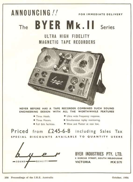
Today, we wouldn't usually consider a piece of recording equipment to be portable if it weighs 45lb/20kg, but 50 years ago this was the case. At the time the Byer "66" and "77" Mk II models in a "portable" package had most if not all of the features of studio console tape machines and specifications to match.
Byer "66" Mk II Features
2. Push button / solenoid operation.
3. Speed options were either 3 3/4 and 7 1/2 ips or 7 1/2 and 15 ips.
4. Four winding speeds in each direction.
5. "Edit" mode to make it easy to thread and cue.
6. The "Edit" mode and winding is controlled by a single rotary switch called the "Shuttle Control".
7. Shuttle monitor control sets the position of the tape lifter, for tape monitoring while winding.
8. Tape threading line on the deck.
9. Slanted "S" tape path for fast threading.
10. Spool locking caps.
11. Each main sub-unit, amplifier, deck, and Auxiliary Spooling Mechanism are 19" rack mounting.
12. Play-Safe key-switch used to lock-out unintentional recording.
13. Remote control socket, for STOP, PLAY, and RECORD functions.
14. Auxiliary spooling unit socket (a unit with motor spacing for 10 1/2" spools).
15. Bias adjustment.
16. 600 ohm balanced input and output.
17. Microphone and high impedance line inputs.
18. Optional in-built AM radio tuner.
Byer "66" Mk II Controls and Indicators
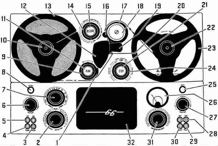
| 1. Tape over-run. | 9. Speed/Power switch. | 17. Pressure roller. | 25. "Mains" indicator. |
| 2. Input selector. | 10. Spool cap. | 18. Cover disc. | 26. Level meter. |
| 3. Unbal bridging input. | 11. "PLAY" button. | 19. Head shield. | 27. Monitor volume. |
| 4. Microphone input. | 12. Triple head assembly. | 20. Tape lift pin. | 28. 600 ohm output. |
| 5. Bal 600 ohm input. | 13. Supply reel. | 21. "STOP" button. | 29. Ext speaker socket |
| 6. High frequ boost/cut. | 14. Shuttle monitoring. | 22. Spool cap. | 30. Headphone output. |
| 7. Radio tuner dial. | 15. "RECORD" push button. | 23. Take-up spool. | 31. Gain adjustment. |
| 8. "RECORD" indicator. | 16. Capstan. | 24. Shuttle control. | 32. Monitor speaker. |

As you can see here the tape recorder is closed up for transport. The case is an early version of the road case that is in common use today. These cases were built to be sturdy, as a friend of mine can testify, one of these tape recorders fell from the rear of his vehicle when the tail gate latch released while he was driving along a main road. Apart from some scratches on the case the recorder still continued to function normally after this rough treatment.

To set up the Byer "66" Mk II for operation the front cover is removed and the rear hinged cover is opened and latched into position. The recorder is then tilted back so that it is in the optimum position for the operator to thread the tape and run the machine. The rear cover like many of the parts of this tape recorder has multiple functions. Setting the operating position of the recorder is the primary function of the cover. However, opening the cover allows ventilation, access to the mains cable and inside the cover are winding hooks for the mains cable.
This unit is the most complete example of the Byer "66" that I have in my collection. It has the radio tuner option and even the original dust cover. The only blemishes are some small areas of surface rust on the hinges and catches.
The tube complement in this tape recorder is: 1 x 5Y3GT, 2 x 12AU7, 1 x 12AX7, 1 x EF86, and 2 x N78. Following serial number 909 the N78s were replaced by EL84s.
If the radio tuner option was fitted then there is also: 1 x 6AN7, and 1 X 6N8. I would like to know if the circuit schematic of the radio tuner was ever published, if you know where I can get a copy please contact me.

Till recently this Byer "66" is the only one that I had seen with an auxiliary spooling unit fitted for 10 1/2" spools but with no spool motors in the main deck. This was probably done to reduce weight.

This Rola 66 Mk II is a recent acquisition and like previous example it is configured 10 1/2" spools. This, however, is not the most interesting aspect of this machine. In the original Byer press release for the 66 Mk II the following statement was made "Any two adjacent speeds may be supplied in a range from 1 7/8in/sec to 120in/sec". Most 66 Mk II machines were supplied as 3 3/4ips and 7 1/2ips or 7 1/2ips and 15ips. Many of the lower speed units had significant wow and flutter as the capstan shaft diameter was very small. This led me question how was it possible to easily implement other speed pairs.

So we come back to the most interesting aspect of this machine. The capstan is belt driven, while this was a departure from normal the design it did give the manufacturer flexibility to offer a large range of tape speeds and have a capstan with a diameter the same as the 7 1/2ips and 15ips speed pair. Also as one ordinary spool motor position is used these machines with speed pairs outside of the normal range would all have to had to have 10.5" spool capacity. The speed pair for this machine is 1 7/8ips and 3 3/4ips, it's also a half track.
