 |
MGEN |
What is the MGEN?
The MGEN or Memory Generator? is a 1k or 2k word program which reads the control tape, loads records that have a verified checksum, and as the data is saved the multiple read/writes that will force a parity error if the system memory is faulty. As the control software is read sucessfully the lights on the measurement buttons on the 5441A display are incremented in a binary count. For unsucessfully read records the tape will be rewound and MGEN will try to re-read those records. In the 5420 software there doesn't seem to be a retry limit, as for the 5423 it is limited to five retries.
MGEN also allows the user to duplicate the control software tapes, verify a newly written control tape, generate and certify test tapes, and tape position control.
Following is the function list available while MGEN is running.
| Key | Description |
| "9" | Duplicate Control Cartridge |
| "8" | Verify Control Cartridge |
| "7" | Load Control Cartridge |
| "6" | Generate Test Tape |
| "5" | Certify Test Tape |
| "4" | Rewind Tape |
| "3" | Position Tape Forward |
| "2" | Select Other Cartridge Drive |
| "1" | Position Tape Backward |
| "0" | Exit to "READY" (SETUP STATE SCREEN) |
| "." | Select Read Threshold for "8", "7", and "5" |
| "GOLD" | 5420A only, Acknowledge flashing "INPUT" light, do light test |
| "X" | 5423A only, Stop tape on error in "8", "7", and "5" |
| "SELF TEST" | Loops the operation of "9", "8", "", and "5" |
| "ANY KEY" | Stops "X" or "SELF TEST" functions |
MGEN is crucial for the system to boot.
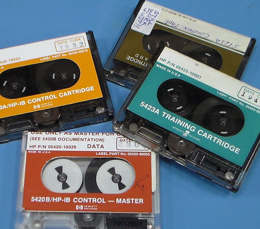
As tapes can sustain some damage over time, multiple copies of MGEN were stored on a given tape, at least two and possibly three. So if the copy of MGEN at the start of the tape doesn't load because of a checksum failure the IBL software will continue reading a tape till it finds the next MGEN record and then try to load that copy of MGEN.
Multiple copies of MGEN on a control tape is an important safety feature as generally tapes are stored in a rewound state and after years of no use the drive band can stick to the tape. If a tape in this condition is not first slowly and gently hand wound and possibly with the drive band removed it is likely that oxide layer from the beginning of the tape will be stripped from the tape. Having at least one spare copy of MGEN on each tape was was a smart idea.
So that I could make sense of what was necessary to load the system memory from other than a tape and correctly start the executaution of the software I had to first capture the MGEN code from tape but not allow execution of the code as I wanted the code directly from the tape not code that had already been running. This is particularly important as the coding techniques used self-modifying code, data and code not in separate areas of memory, and minimising memory usage by using an opcode as part of a program sequence and then the same opcode is used for a data constant by another part of the program.
To load only MGEN a modified version of the IBL was written, see IBL. Then I was able to load and store the MGEN for 5420A, 5420B, and 5423A.
The next step was to disassemble a copy of MGEN, I started with the 5420B version of MGEN as it is a newer version than the 5420A and the 5420A tape that have won't load all the system software. Also the 5423A MGEN is longer and I thought I may be easier to see what was done with the "simpler" system. I should add that I was still debugging the disassembler at this stage but working on real code helped me to in the debugging process.
With MGEN disassembled I found the exit point to the main system software and equally importantly I found a few instructions prior to the exit I found a subroutine call which was to a subroutine which performs the "Light Test". The Light Test is important as it is used as a marker to the progress of the loading process and more importantly forces a reset of the system I/O dvices. This particular Light Test is the last one before the System Setup page is displayed and for the 5420B software the entry point (P-reg or Program Counter) is at 24017oct. Currently, with the software and hardware I've developed a copy of the 5420B software can be uploaded from a Windows PC to the 5420 and software execution is initiated at location 24017oct and the Signal Analyzer will start up!
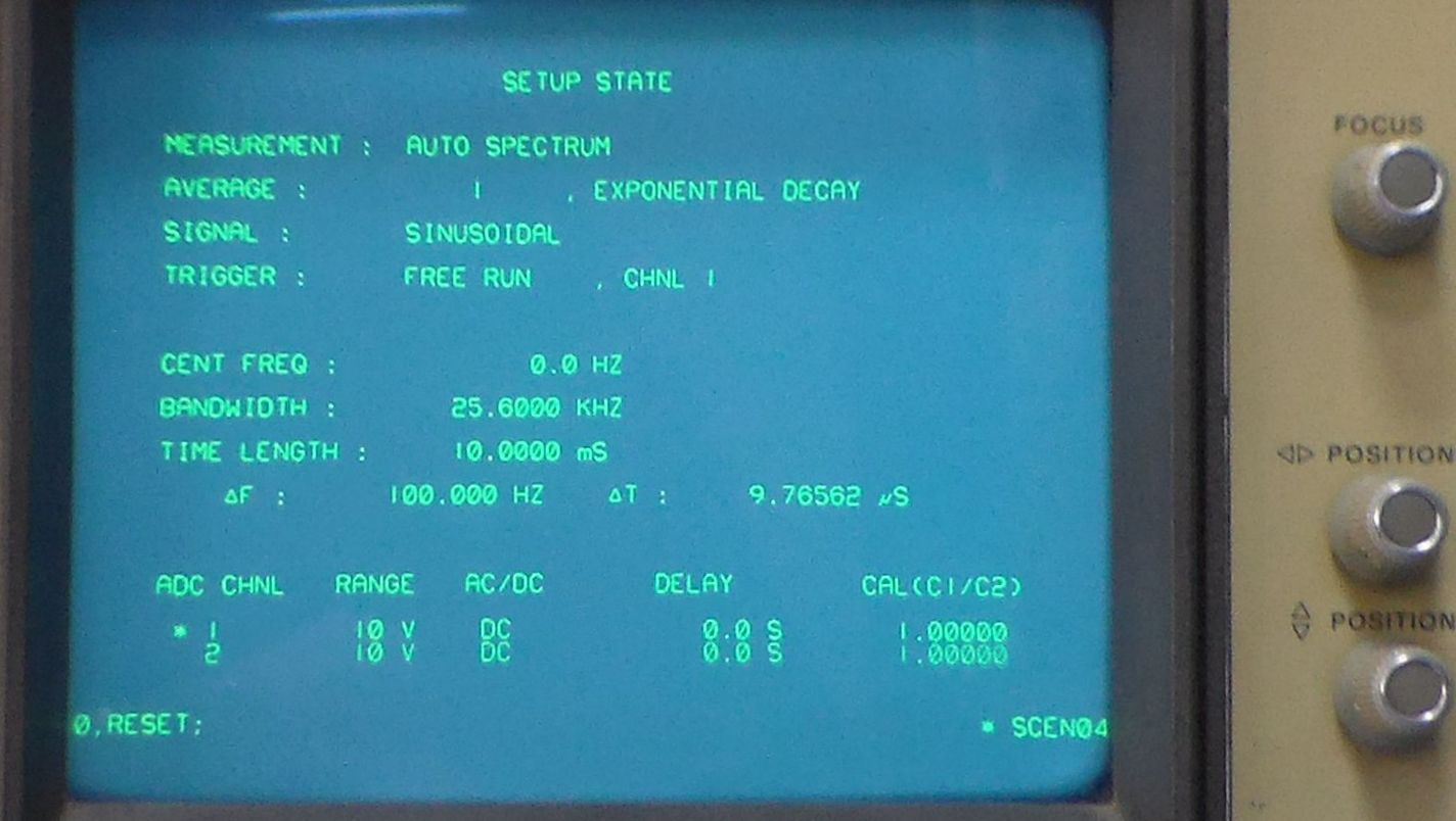
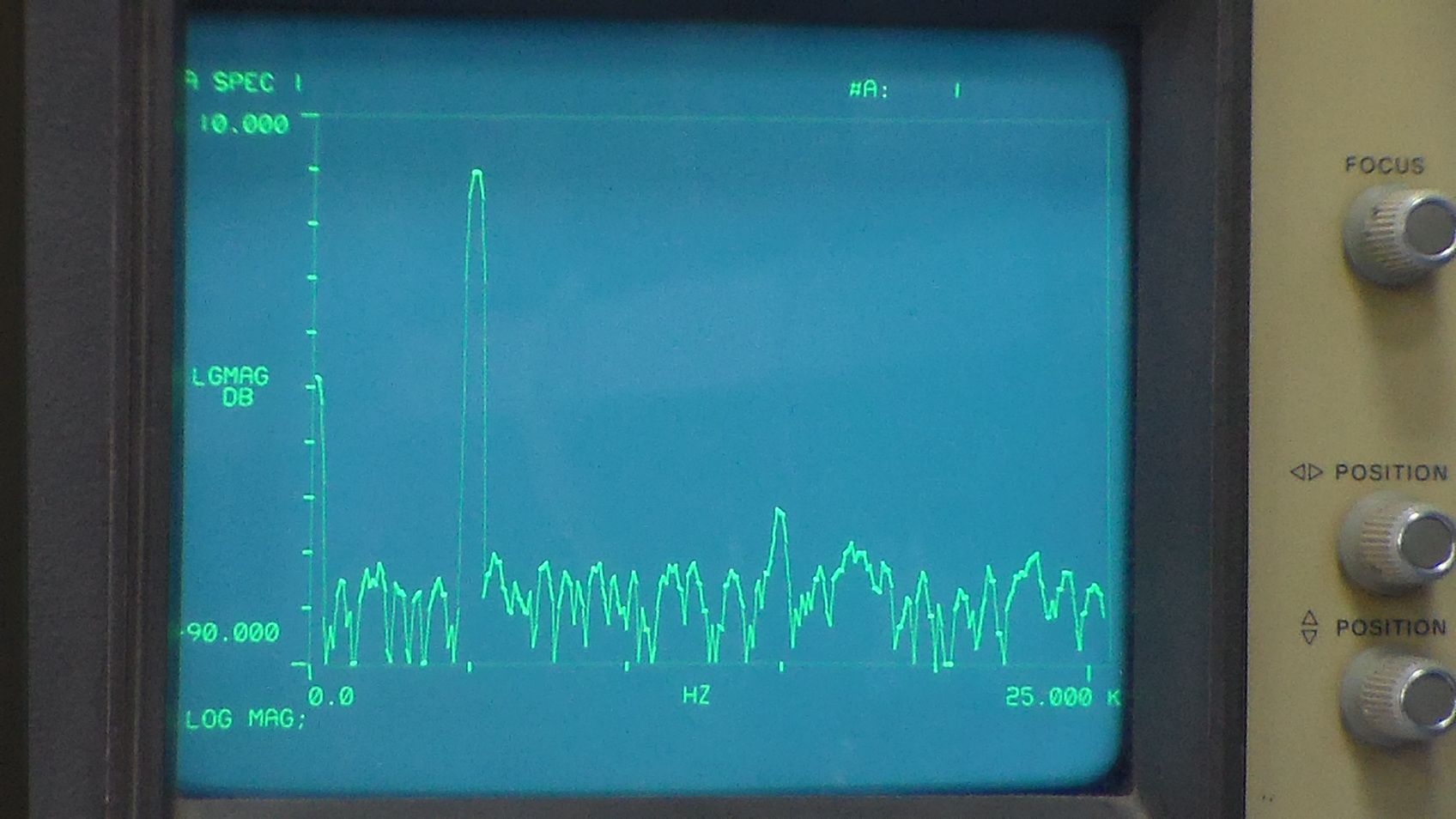
Above is the "SETUP STATE" display for the 5420B control software and below is a 25kHz spectral display in log magnitude format with a 5kHz signal applied to the channel #1 input.
To ensure that I have fixed any errors in the source code that I've generated while working on the disassembly and commenting of the code for the 5420B MGEN I regularly reassemble the disassembled code to verify it against the original code from tape. Without an assembler for the 21MX processor this task would have been more difficult.
I've used the ASM21 assembler in this project, thanks to Eric Smith, Tim Riker, and Lyle Bickley who have made contributions to ASM21, I have made some small additions to ASM21 specific to the 5420/5423 systems and I found a small bug relating to some of the I/O instructions. There is a link at the top of this page to the version of ASM21 I'm currently using.
The next step is to build an I/O card with flash memory on it which will save a copy of the system software so that the equipment will boot from the flash rather than a tape or a PC. There is one spare I/O card slot in the rear of the 5443A Keyboard/Control unit (21MX processor) which may be where the software can be stored.